As part of the LLEC energy demonstrators, two battery energy storage systems will be installed on the FZJ campus. These battery systems are quite different from each other in terms of storage capacity and power because this makes them more interesting for the LLEC science case. The first battery is a high-energy battery system with a capacity of 2600 kWh and a power of 595 kW. The second battery is a high-power system with a capacity of 500 kWh and a total power of 1500 kW. Note that kWh is actually a unit to express (electrical) energy consumption for which e.g. the energy company charges you every month some money. However, in this context, it is more common to speak about capacity. The difference between a high-energy and high-power battery is that a high-energy battery has a high number of kWh’s per unit of weight. High-energy batteries are, for example, typically found in battery electric vehicles and laptops to allow long-range driving and user time, whereas high-power batteries are often used in hybrid electric vehicles and mobile power tools to (shortly) boost an electric device with high power.
At the start of the project, the capacity and power of both batteries were calculated by IEK-10 such that these fit into the LLEC research domain. The batters, in which the energy is stored and from which the energy is delivered, are for both systems based on state-of-the-art Li-ion technology. At present, this is the most common battery technology because of the relatively high energy/power density and long life. For example, in the current mobile consumer electronics and electric vehicles Li-ion technology is applied.
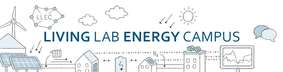
It was decided to install both battery systems in the open air. Because it is not possible to install these batteries at a random location on the campus, a suitable location had to be found, which turned out to be a challenging task. For example, such a system cannot be installed on a position where cables/pipes are already running underground or, on a potential construction site for something else. It is also not allowed to deforest large pieces of land because of obvious environmental reasons. For efficiency reasons, the systems should not be located too far from an electronic connection point and, moreover, the location should comply with the FZJ Masterplan. In the end, we found a location for the high-energy battery system in the vicinity of our student laboratory, JuLab (building 04.11), on the lawn between the two buildings 04.6w and 04.5u. Other LLEC demonstrators, such as a small wind turbine and hydrogen facility for seasonal energy generation/storage will be installed in this area as well. The planned positions for these LLEC demonstrators are indicated in Fig. 1.
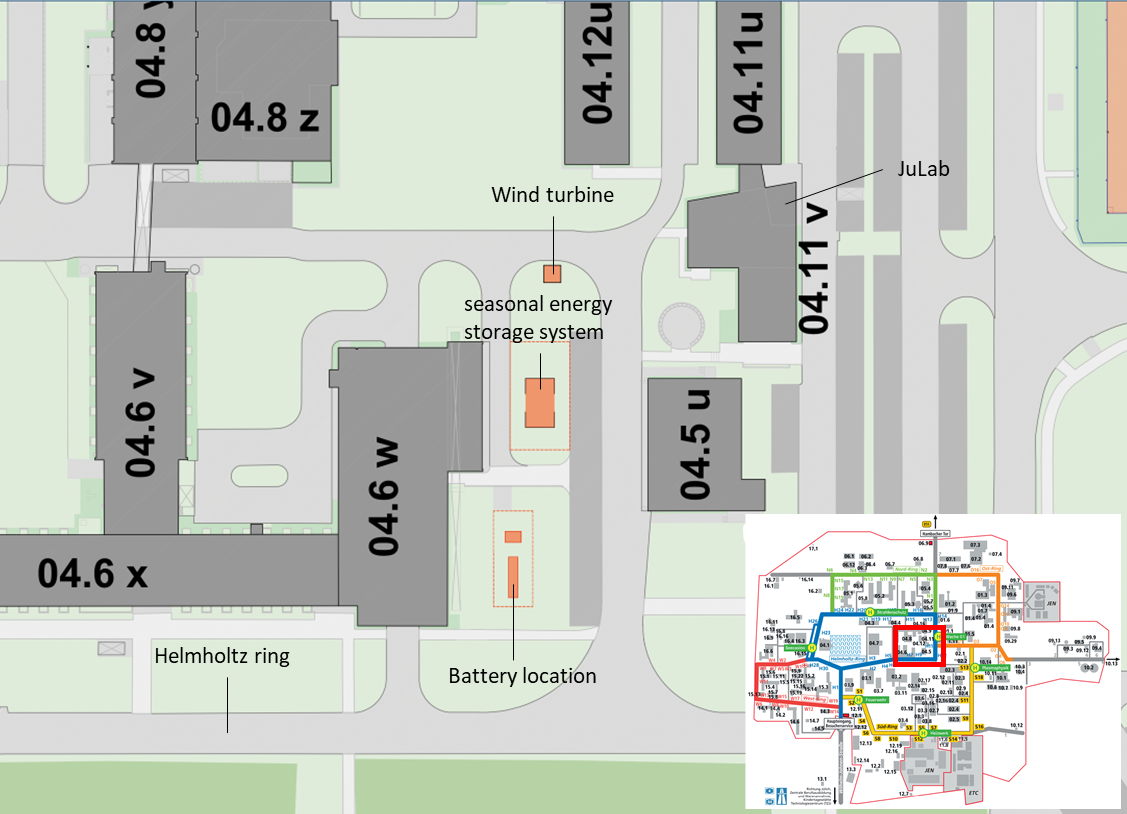
Fig. 1. Section of the FZJ campus in which the location of the high-energy battery and other LLEC demonstrators are indicated. The inset shows the complete FZJ campus in which the red rectangle indicates the relevant section for the high-energy battery. Source: Civil Engineering (B-B) Forschungszentrum Jülich.
For the high-power system a site at the left-hand side of building 10.11u (see Fig. 2) has been selected as a suitable location as this battery will be connected to the upcoming HEMCP/ELECTRA (10.22u) building, an office and laboratory building that will be used for research on electrochemical energy storage/conversion devices. I am very thankful to my colleagues from the civil engineering (B) and technical (T) departments for the help in the search for suitable locations. More details about the location of the batteries and other LLEC demonstrators can be found in the blog post of Susanne Hoffmann.
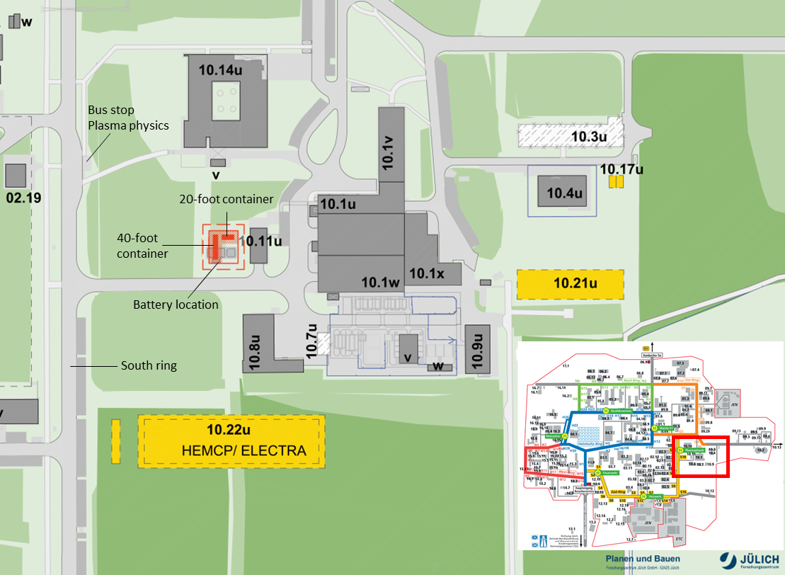
Fig. 2. Section of the FZJ campus in which the location of the high-power battery is indicated (orange color). The inset shows the complete FZJ campus in which the red rectangle indicates the relevant section for the high-power battery. Source: Civil Engineering (B-B) Forschungszentrum Jülich.
Because the battery systems are relatively expensive, a European tender was mandatory. It was therefore necessary to compose a specification of services, in which the requirements, boundary conditions, and restrictions were described. These items are not only concerned with the battery itself, but also with the environmental conditions, such as construction site, civil- and electric engineering requirements, safety, etc. For that reason, the civil engineering, technical and safety departments supported in composing this document. For the technical (battery) part of the specification of services, we also received assistance from ISEA (RWTH Aachen) because they wrote a similar document in the past for their own stationary battery storage systems. After finishing the specification of services, it was sent to the purchase department. They published it on a portal which is accessible by companies that offer battery systems. These companies then prepared an offer, which was tuned to the specification of services, and sent their offer to us. All offers were evaluated with help of an evaluation matrix in which credits are assigned to various subjects, such as price and technical properties. Both battery systems were ordered from the company that received most credits.
The company that received most credits for the high-energy system will deliver and install a 2600 kWh / 595 kW battery storage system. For confidentiality reasons we are, unfortunately, not allowed to show any figures or producer names, yet. More information will be made available as soon as the system is taken into operation. Anyway, the high-energy system contains various battery modules, inverters, a customer interface, and a cooling system. These components, which are accessible through various doors, are packed into an enclosure. The manufacturer offers a warrantee of 10 years on these parts and claims that 75% of the capacity and performance are guaranteed for 120 months or for 1500 full cycles. The transformer, high-power switches, and required measurement unit are installed in the transformer station. The high-energy battery takes up an area of about 11 m2. This is excluding the transformer station, which will occupy another 8 m2. For safety reasons, the system will be surrounded by a fence.
The high-power battery system (500 kWh / 1500 kW) is made by Riello Power Systems. They use their own inverters and battery cells from the Japanese company Yuasa. This system consists of two containers. The larger, 40-foot container, contains the power electronics, power distribution system and control units and the smaller 20-foot container contains the battery modules and a fire extinguishing system. Both containers are cooled internally by cooling units. A schematic overview of this system is shown in Fig. 3. The containers will be positioned perpendicular. A perpendicular container orientation makes them somewhat more convenient to show to visitors. The system manufacturer provides spare parts for a period of 10 years and guarantees 70% of the initial capacity after 11.000 cycles with a discharge depth of 100%. Quite unique is that the battery cells can be discharged with a 6 C-rate and charged with a 2.5 C-rate. Note that a 1 C-rate represents a current with which the cell can be (dis)charged in one hour.

Fig. 3. Schematic example of the Riello stationary battery storage system containing a 20-foot (left) and 40-foot (right) container. Source: be.storaged GmbH and Riello Power Systems GmbH.
At present, we are preparing the building application forms for both battery systems in collaboration with the company that performs the planning for both units. The building application form contains a structural analysis of the fundament, a fire protection report, and an ordinance on systems containing water-polluting substances. This document will first be evaluated internally and then sent to the municipal in Jülich. If the officials in Jülich approve the application forms, we will receive the building permits and then we can start installing the battery systems. In addition, a noise analysis will be performed and preventive measures will be taken to minimize the risk of disturbing sensitive laboratory experiments.
According to the current planning, civil construction work will be performed at the end of Q4 and at the start of Q1 2021 for both systems. After installation and performing tests, we can take the systems into operation as of the beginning of Q2 in 2021. We will inform the surrounding institutes in advance before construction work starts.
When the high-energy battery is in operation, it will be used for maintaining the relationship between supply and demand in the decentralized LLEC energy system. That means that electricity is taken from the grid when sufficient renewable energy is available (from e.g. the LLEC PV systems) and fed-back into the grid when the demand increases or the production of renewable energy declines. In this case the grid can be balanced. Furthermore, it is possible to save money by storing energy when the electricity price is low, and using it when the electricity price is high.
The high-power battery will be used for peak shaving. That means that high-power loads in the supplying grid can be reduced by (shortly) injecting electric energy from the battery into the grid. This reduces the load and, consequently, stabilizes the grid. Moreover, it can also reduce the electricity bill because no extra fees need to be payed anymore when the load exceeds a certain value. At the same time, the high-power battery will be used as an uninterruptable power supply (UPS). The UPS system is a so-called online or double-conversion UPS. This means that it is designed in such a way that there will be absolutely no interruption in power supply in case of a power outage. Ultimately, the intention is to connect the UPS to a part of building 10.22u (ELECTRA). However, because building 10.22u is not finished at the start of battery operation, the UPS will be connected as an interim solution to building 10.14u.
Both battery systems will be examples of integrated novel storage technologies in decentralized energy systems. Valuable insights into the performance and lifetime under real operating conditions can be obtained, which will be relevant for the innovation of stationary energy storage systems. By developing models of these battery systems, we can simulate the operating conditions and aim for an energy-optimal, cost-efficient, and safe operation of the total LLEC energy system. The institute in which I work (IEK-9) will therefore closely collaborate with other FZJ institutes, such as IEK-10, which focusses on the optimal design and operation of integrated, decentralized energy systems.
3 Responses to “High-energy and high-power batteries for the LLEC project”